Helical Piles for Seawalls, Bulkheads & Docks
Helical piles (also called helical piers or screw piles) for seawall stabilization, bulkhead tiebacks, dock foundations and marine platforms. Installed by hydraulic rotary drive at near-zero vibration, with a recorded torque and calculated capacity for every pile.
Worked example, not a site record
- Installation torque, T (illustrative)
- 8.0 kN·m
- Kt, 89 mm shaft (AC358 default)
- 23.0 m⁻¹
- Ultimate capacity, Qult
- 184.0 kN
- Factor of safety
- 2.0
= Allowable load, in this example92.0 kN
Try other torquesFoundations that go in while the waterfront keeps working.
Both methods put plant on the water. The difference is what the neighbors feel while the piles go in, and what your engineer gets back: a hammer and a sampled capacity check, or a rotary drive and a capacity reading for every pile.
Driven or cast foundation
- Step 1:
Crane barge and hammer on site
Heavy plant alongside the working waterfront.
- Step 2:
Piles driven
Impact or vibratory hammer: noise and vibration reach adjacent structures.
- Step 3:
Neighbors monitored
Vibration monitoring of adjacent structures, where required.
- Step 4:
Capacity checked on a sample
Load or dynamic testing on selected piles, where specified.
- Step 5:
Caps cast and cured
Concrete caps or grout gain strength before loading, where used.
Helical pile
- Step 1:
Crane and rotary drive on site
The hydraulic drive hangs from a crane. No hammer.
- Step 2:
Pile screwed in
Near-zero vibration next to live structures.
- Step 3:
Torque recorded
Continuously, on every pile, as it advances.
- Step 4:
Capacity read for every pile
Final torque converted to capacity before the crew leaves.
- Step 5:
Loaded the same day
No curing wait for the pile itself; caps, where used, cure like any other.
Steps, not days. Durations depend on your site, soil and access, and we set them out in the proposal.
What your engineer gets.
Capacity on a helical pile is read, not assumed. Installation torque is recorded on every pile and multiplied by a published torque factor for its shaft size. Here is the arithmetic, and the record it produces.
Worked example, not a site record. The torques are illustrative; Kt is published and the rest is arithmetic.
- Installation torque, TIllustrative — picked above
- 8.0 kN·m
- Torque factor, KtAC358 default, 89 mm (3½ in) shaft
- 23.0 m⁻¹
- Ultimate capacity, Qult≈ 18.8 tonnes
- 184.0 kN
- Factor of safetySet by the engineer of record
- 2.0
- Allowable load≈ 9.4 tonnes
- 92.0 kN
Capacity follows the torque reached. Your engineer sets the design torque, the shaft size and the project Kt; the full table of published Kt by shaft is on the method page.
Recorded for every pile
The fields each pile’s capacity record carries.
- Installation date
- When the pile went in.
- Position
- GPS coordinates, against the pile layout.
- Soil classification
- As encountered at the bearing depth.
- Torque log
- Final torque averaged over the last three helix diameters.
- Kt applied
- The value used, and where it comes from.
- Calculated Qult
- Torque × Kt, for that pile.
- Factor of safety
- As set by the engineer of record.
- Pull test
- On selected piles, where the project calls for it, to confirm the estimate.
The plant, and the record behind it
Our installed record is marine: mooring anchors on a working mussel farm, and floating-dock and boat-mooring anchors off a hotel in Erdek. Commercial piles go in by the same installation method, and every pile gets the same torque record.
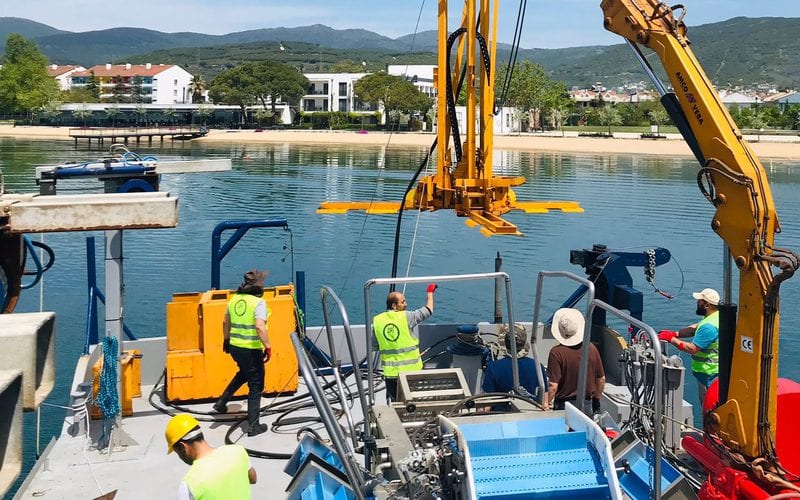
How a helical pile holds on a working waterfront
A helical pile carries load through steel helix plates bearing on soil below the weak surface layers and below the site’s expected scour depth, so currents and surge do not undermine it. Axial capacity is the engineered figure, calculated from installation torque; lateral load is carried by the shaft’s bending stiffness and the passive resistance of the soil around it. Installation needs no excavation and no dewatering.
What contractors and engineers ask before they commit
Send us the drawings. We’ll specify the piles.
Send your soil report, structural drawings and schedule. An engineer replies within 24 hours with questions and a first read; the full proposal follows within two business days.
Get a Project Estimate